SMART DOG MININGTM
It
takes a smart dog to find hidden treasures
An Introduction to a Dense Medium Cyclone Circuit
For processing ores and coal a circuit that is seeing greater
interest and use is the dense medium cyclone circuit.
It is seeing use in diamond operations and heavy mineral
processing. Its use in
coal goes back to the middle of the last century (circa 1945).
A typical dense medium cyclone circuit is shown in the attached
sketch.
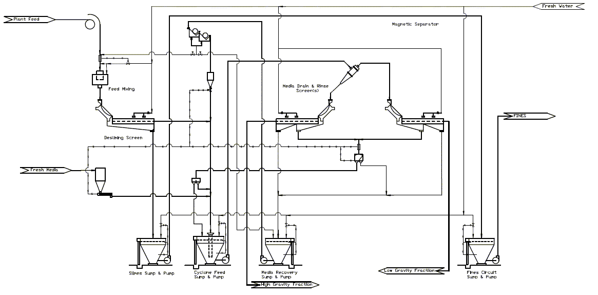
This circuit consist of an ore feed, a set of desliming screens to
pre-size the feed to the cyclones, a cyclone feed sump, dense medium
cyclone(s), media drain and rinse screens, and a media control
circuit. It is often
combined with a fines circuit to process material of a finer size.
Dense medium (sometimes called heavy media) cyclones were developed
during World War II by the Dutch State Mines.
The original application was for coal cleaning.
A cyclone pilot plant was successfully operated in Europe
during 1945, and observed by H. F. Yancey of the US Bureau of Mines
(USBM, now part of the Department of Energy (DOE)).
Mr. Yancey started a similar program for the USBM, with a
published report in 1948.
Cyclone plants quickly became widely used in Europe, but the
first United States plant was not built until 1961.
Today dense medium cyclones are the most common coal cleaning
device. For hard to
clean coal (+10% near gravity material) in the size range of 50mm to
0.5 mm (28 mesh), the dense medium cyclone is widely used.
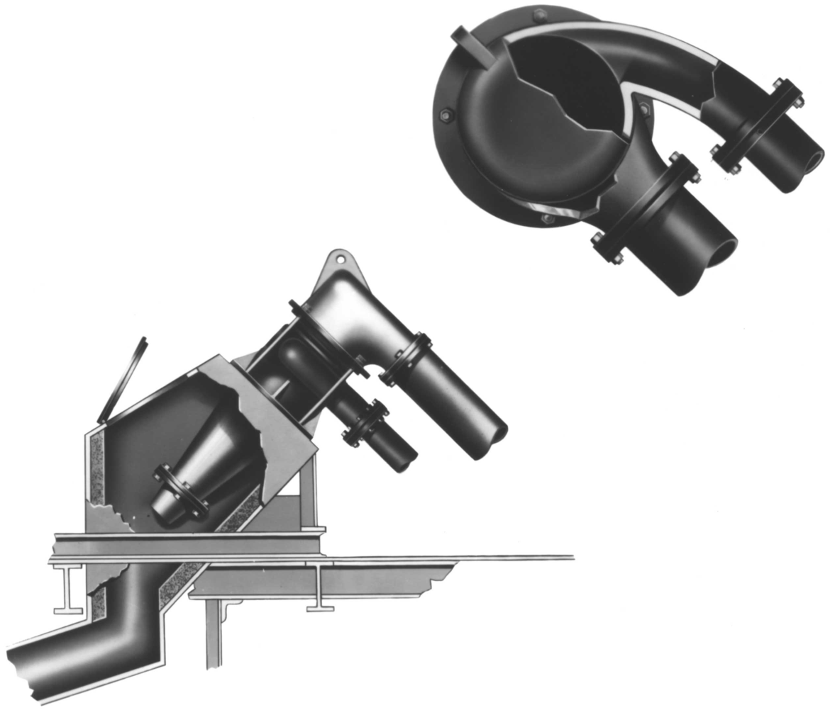
In its operation, a slurry of ore or coal and media
(magnetite dispersed in water) is admitted at a tangent near the top
of a cylindrical section that is affixed to a cone shaped lower
section. The slurry
forms a strong vertical flow.
Under the force of gravity, the higher specific gravity
particles, move along the wall of the cone and are discharged at the
apex. The particles
having a lower specific gravity move toward the center of the
cyclone. In the center a counter rotating vortex moves the light
fraction upwards. The light fraction is discharged through the
vortex finder. The
dense medium cyclone functions efficiently even with large amounts
of near gravity material in the feed.
The size of a dense medium cyclone is usually expressed in
gallons/minute of pulp capacity to the inlet.
Alternatively as the tons/hour of raw coal feed to cyclone.
Dense medium cyclone sizing depends on how much pulp you can
feed through the inlet.
Once in the cyclone you have to make sure that the overflow
and underflow can handle the amount of material reporting to each.
All of this while maintaining the needed efficiencies to make
the separation desired.
Dense medium cyclones behave similar to classifying cyclones in
volumetric handling capacity.
And any general capacity information for cyclones will apply.
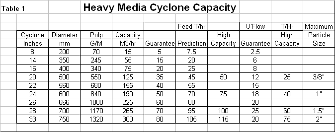
A latter section of this article describes general cyclone
sizing. Specifically
for dense medium cyclones the attached capacity table (Table 1)
should be used. This
chart is based upon the information over collected from many
projects.
EXAMPLE
The following is an example of sizing and selecting a dense medium
cyclone. It is included
for reference only.
In actual practice many different factors can cause the
specific selection to change.
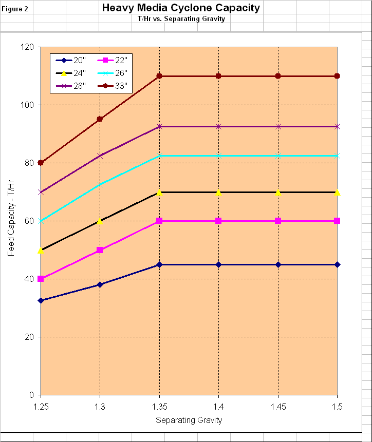
200 T/hr of raw coal
1 " x 1/4" (25 mm x 6.5 mm)
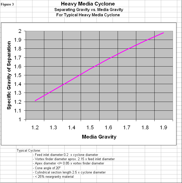
1.50 separating gravity
80% (at 1.50 Sp.Gr.) reporting to clean coal.
Calculation of a dense medium circuit is the determination of the
amount of media circulating in that circuit and the amount of media
(magnetite) lost to dilute media.
![]()
Where Dn is the average grain size of the solids (coal or
refuse) and SG is the specific gravity of the solids.
This is the solids in the feed stream to the drain and rinse
screens or sieve bend.
T/H is the solids flow rate in tons per hour to the D&R device.
G/M is the gallons per minute of pulp.
C/C adhering media + Refuse adhering media + Level Control Volume +
Rinse Water + Products surface moisture = Total dilution
o
40+
years’ experience in the mining industry with strong mineral
processing experience in Precious metals, copper, industrial
minerals, coal, and phosphate
o
Operational experience in precious metals, coal, and phosphate plus
in petrochemicals.
o
Extensive experience studies and feasibility in the US and
international (United States, Canada, Mexico, Ecuador, Columbia,
Venezuela, Chile, China, India, Indonesia, and Greece).
